The Problem With Scanning
Relying on a tech to manually scan reports into our system was a non-starter for us for a couple of reasons. First, we didn’t want just a picture of the report. To be worth anything for outcomes analysis, we actually wanted all of the hundreds of data points and metrics the report contains, such as refraction data, pupil size, flap thickness, Zernike coefficients and keratometry readings. An electronic scan gives us none of this.
Second, EMR companies expect the tech to be responsible for locating and manually moving the scanned report into the proper patient folder in the EMR system. This is ridiculous given the capabilities of modern computing technology, and is particularly egregious because it’s only a matter of time before the tech makes a mistake and places a vital report in the wrong patient folder, effectively losing the data forever and violating HIPAA by burying one patient’s information in another patient’s medical report.
Once a report is scanned in, some practices might try to use optical character recognition to “read” the letters and numbers in an attempt to extract them for analysis, calculation of percentages, etc. Though traditional OCR is an elegant concept, it has several limitations. First, in most cases OCR is not 100-percent accurate in recognizing letters, numbers and symbols. For our purposes, where we’re dealing with surgical lasers that actually treat patients, even 99-percent accuracy isn’t good enough. Second, some fonts used by printers use the same symbol for different characters. For example, the Arial font frequently used in medical reporting uses the same symbol for an uppercase “I” that it uses for a lowercase “l.” This would wreak havoc as you try to get your system to perform a mathematical outcomes analysis of your LASIK patients. Finally, OCR typically works in a setting in which the data you need is always found in the same data field in the printed report. However, some reports, such as those produced by AMO’s excimer laser, for example, print similar data in different locations. Such a situation wouldn’t work well with traditional OCR.
Our Solution
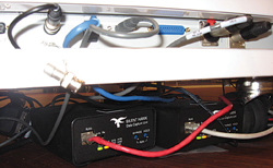
The first part of our device connectivity system consists of a small (3 x 4 x 6 inch) data-capture device from a company called JADTech (Torrance, Calif.). The device slides underneath our lasers and refractive diagnostic equipment and patiently waits for the user to hit the “print” command. When this is done, the JADTech device emulates a printer and reads the streamed printer control language that the computer would use to print something on paper.
The second part of the system is the extraction of the vital patient data from the PCL code. We had special software written that takes the PCL and extracts all the pertinent data from it and then formats it instantly into commonly used formats such as tab-delimited, comma-separated and the format mandated by the Digital Imaging and Communications in Medicine, or DICOM, standard. Therefore, once the report file is captured, key data is extracted and used to name the file. The software then automatically imports the extracted data into the appropriate data tables in the database, creates a database link to the now uniquely named report and moves it into the correct patient folder in the EMR. This is all accomplished within seconds of the technician pressing the print button on the device console.
|
System Benefits
In addition to the basic benefit of instantly filing the data in the patient record and in a format that we can analyze afterward, we’ve built other features into it that are mandatory in a medical practice.
• Security. Some connectivity solutions used with EMR systems use a universal serial bus interface. The risk with USB is that it allows bidirectional data transfer, meaning that hackers could use it to insert viruses or malware into the excimer or femtosecond laser. Iranian scientists learned about the hazards of USB bidirectionality the hard way when a USB device was used to insert the infamous Stuxnet worm onto their uranium enrichment centrifuges, crippling their nuclear program.
Though we’re unlikely to encounter a virus as formidable as Stuxnet in our practice, we can’t compromise patient safety with the connectivity devices we use. So, we’ve elected to use a device that uses both hardware and software firewalls that make data transfer backward from our network to our laser systems impossible. In fact, the same security device is actually used in U.S. nuclear missile silos and nuclear reactor facilities. Also, if we need to transfer any data captured by our device to a remote location outside of our secure network, the software has a built-in method for 256-bit encryption so the data can be safely emailed or securely moved to the cloud.
• Always on. Our system runs on any enterprise-level server and is always on. It is operational across any local area network or wide area network and will also operate using a secure virtual private network. The peripheral hardware attached to each laser or diagnostic device is also operating 24/7. In more than two years of operation, none of the peripheral devices has failed or required rebooting.
• Universal connectivity. We wanted our solution to work for every device that we encountered in our clinic and surgical suites. With the device that we elected to use, we can use the identical hardware and software to connect to anything ranging from so-called “legacy” systems (i.e., old, outdated hardware) that are common in medical settings, to state-of-the-art diagnostic or surgical devices.
Though we can interface with most devices, we can’t yet interface with the Alcon WaveLight excimer laser, the Alcon/WaveLight FS200 femtosecond laser for flap creation or the Ziemer Femto LDV femtosecond laser. However, if and when we are able to install the system in a beta site with these instruments, we’d be able to capture the data from those devices, as well.
• Scalable. We have two office locations, so we needed a system that could be used reliably at both sites. With the system we selected we can connect anywhere from 1 to 99 peripheral data capture devices to a single server that is running the core software. The server does not even need to be located locally, as the capture system will readily communicate across a WAN or VPN, thereby markedly reducing expensive hardware or software costs.
• OR friendly. Some connectivity systems we had looked at require a computer workstation, keyboard, mouse and monitor for each device that requires data capturing, including laser systems in your OR. This requirement quickly creates an unwieldy, unworkable workspace that’s cluttered with 110-volt wiring and cables and monitors that interfere with iris recognition capture. Our small capture device fits on the laser or other device and is connected to the network with one Category 5 cable, minimizing clutter.
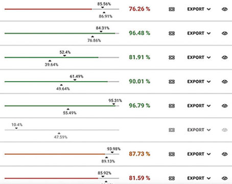
• Helps make my results better. Once I began to collect the set of data from my lasers and preop equipment that I had been missing, I was able to create a program to analyze the numbers in ways I couldn’t before. I was unable to analyze them previously due to the sheer magnitude of the task involved with manually inputting thousands of Zernike coefficients, wavefront capture diameters, Q-values (corneal asphericity) and other data points that were photographed in the clinical record but ultimately ignored because they couldn’t be used for statistical queries. Now, though, equipped with this data from hundreds of patients, I can establish search parameters such as, “Every patient between -1 and -6 D with at least 0.5 D of astigmatism, keratometry between 45 and 47 and spherical aberration and coma terms greater than 0.3 µm,” and the system will instantly give me their results. I can understand the complex relationships between vision metrics and my final results.
Being able to instantly record, sort and then analyze my surgical outcomes without the need for manual entry of data parameters brings my refractive surgery practice closer to the evidence-based medicine ideal, which is the application of population-based vision outcomes data to the care of the individual patient. It’s startling to think that, though we refractive surgeons routinely review sphere, cylinder and visual acuity data of our patients, when it comes to analyzing the clinical effects of higher-order aberrations like spherical aberration on lower-order aberrations like myopia, we have failed to derive a useable algorithm in more than 10 years. With a system like this, we will be able to see these relationships, and laser manufacturers may even be able to use what we learn to adjust how their lasers treat certain combinations of HOAs and LOAs to optimize results. REVIEW
Dr. Will is in private practice. For surgeons interested in elements of the system and how they might apply to their instruments, he can be contacted at drwill@willvision.com. A longer discussion of refractive surgery’s MIS challenges appears on Review’s web version of the article.